


Case study: Florence, Italy
Overview
- ATAF is the Municipality-owned bus operator of the City of Florence, serving the Metropolitan Area and some hinterlands towns.
- Since 2005, services are provided under Service Contract to the Province of Florence, for which ATAF joined with Li-nea and some smaller operators in a special purpose entity.
- The Contract has quantitative and qualitative performance requirements, in particular in relation to volume of service and punctuality. It also places quite extensive service and event reporting requirements.
- ATAF first introduced AVLC in 1984 to about 100 of its buses. The AVLC was updated in 1996 and extended to the full fleet of about 400 buses. This included GPS, trunked mobile radio, and enhanced AVLC functions.
- A new procurement was launched in 2006 for a total AVLC replacement, at-stop RTPI units, and internet/mobile travel information applications. It also procured a limited amount of video-surveillance and traffic signal priority facilities, which may be extended later.
- Phased deployment has commenced in 2009 with the new AVLC Control Centre already fully operational. It contains a major functionality upgrade.
Scope of the Case Study
This case study deals with the ITS implemented at ATAF, the Municipally-owned bus operator in Florence, Italy. ATAF operates the bus services in Florence area as part of a special purpose group (S.C.a.R.L) that also includes Li-nea, the other major bus operator in the area.
The ITS which is currently being deployed at ATAF is also being deployed at bus operator Li-nea, having been procured under a common process from the same supplier, although separate contracts are signed for the systems installed at each operator. ATAF is the focus of the Case Study as regards motivation, deployment and experience, whereas the technical systems are common to both operators.
The Case Study does not cover the ITS implemented at the single tramway line in Florence, which is operated under separate contract and different operator.
Context
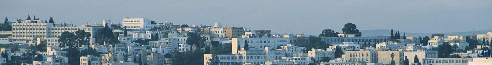
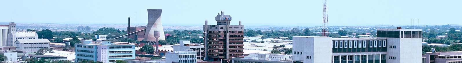
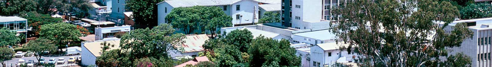
Florence is the main city in the Province of Florence and the capital of the Region of Tuscany. It has a population of approximately 400,000 people, and has a number of small towns in its hinterland that are connected to Florence by local public transport services.
Florence is a historic city with very high numbers of tourists throughout the year. The city centre has relatively narrow streets that permit but also constrain public transport services. The arterial roads from the city centre are also quite narrow, with relatively low running speeds and the high risk of delays.
Until 2008, public transport within Florence was provided entirely by bus. In 2010, a tramway line (Line 1) was opened. There are currently no works underway for further lines. While the tramway has absorbed some of the bus business, bus is still the primary passenger transport mode for Florence and will remain some for the foreseeable future.
Public transport to/from Florence is provided by long-distance and regional buses, and mainly by regional trains. The regional trains provide connectivity to many of the hinterland towns, providing an extensive commuter rail network, although it does not fully meet the overall commuters demand.
Institutional Framework
For the purpose of public transport, there are four relevant levels of administration in Italy, with the following hierarchy:
- National Government
- Regions
- Provinces
- Municipalities
Thus, the Municipality of Florence is within the Province of Florence, which is within the Region of Tuscany, a region of Italy.
Institutional and regulatory reform of public transport has been underway since the late-1990’s. The primary aspect of this reform has been to delegate the responsibility, funding and regulation of local passenger transport to the Regions.
The Region is responsible for strategic passenger transport planning, and for the budgetary matters. The Region of Tuscany is responsible for the passenger transport in Tuscany, which includes the city and hinterland of Florence. The Region plans and budgets according to ‘transport basins’, of which there are 12 in Tuscany. The public transport is procured according to these transport basins. The ‘basins’ follow administrative boundaries, so it is possible that more than one transport ‘basin’ would form the procurement lot.
The passenger transport services are operated under service contract, following a procurement process. The procurement and assignment processes are carried out by the Provinces, including the Province of Florence which covers Florence city and its immediate hinterland.
In 2005, the public transport in Region of Tuscany was procured and assigned for the first time. The Provinces within Tuscany region carried out the procurement and entered service contract with the winning operators. The Metropolitan area of Florence was one of the service areas.
In Tuscany, there were about 40 public transport operators engaged in the scheduled services market, of differing sizes and differing forms of ownership. None of the operators was big enough to take on the procurement lots, meaning that the operators needed to make alliances to do so.
Operator Structure
The public transport services operated under the service contract for the Florence area are carried out by a ‘S.C.a.R.L.’, which is a special-purpose entity in the style of a joint-venture. This entity takes on the contractual commitment to deliver the services and the collective administration with the Province of Florence, while maintaining their corporate independence.
The S.C.a.R.L for Florence consists of ATAF, Li-nea, and a number of smaller bus operators. In essence, it is a co-operative venture without internal competition, within which the responsibility for the individual routes have been assigned to the various operators, the administrative and financial mechanisms are agreed internally, and the mechanisms for service delivery and accountability have been established. All ownership of assets, responsibility for investments, staffing and organizational matters, and financial responsibility remains with the individual companies.
ATAF has a fleet of 443 buses, Li-nea has a fleet of 93 buses assigned to the Florence service area.
ATAF operates entirely within the Florence area. It has three depots.
Basis of Service/Route Award
Passenger transport in the Florence area is provided through a service contract with the Province of Florence.
A global contract is awarded following a public procurement process. In 2005, there was only one compliant bid, being that of the S.C.a.R.L which included ATAF and Li-nea.
The first (current) Contract is for a 5-year period with provision for an extension of up to one year, after which it must be retendered. This is due in 2012 as the extension is utilized.
Permits or Contracts
All scheduled services are operated under a global Service Contract to Province of Florence.
- The service contract specifies the following key items:
- The required network
- The minimum service levels
- Quantitative performance criteria, including
- volume of supply compared to planned
- punctuality
- Qualitative performance criteria, including safety
The Contractor is expected to do the detailed route planning and scheduling within the network and supply parameters. The Contractor has considerable scope to propose adjustments to the services, but always requires the approval of the Province. The Contract has provision for variation of the volume of work of up to 20%.
The financial basis of the contract is:
- the contractor retains the revenue
- the Province pays an agreed sum per kilometer operated
- penalties are applied for below-criteria performance, with possibility of up to €10,000 per day (if the performance becomes worse than that, it is more likely to be dealt with under the warning/termination mechanisms)
- no ‘forgiveness’ is allowed for lost-km due to traffic in payment terms
- there is no applicable bonus
The Province of Florence has the following relevant requirements relating to performance and monitoring:
- The Contractor must provide records of the service supply and quality
- The Contract must provide a record (log) of all services, and in particular of all lost trips, delays, incidents
- The Contractor must provide an explanation of every trip which was not operated, or which was only partially operated
The Region has recognized both the heavy reporting burden this places on the operators, and the value of the information to both the Region and the Provinces. As a result, the Region has funded AVLC for all 12 Transport ‘Basins’. The Region funds 80% of the overall cost, with the balance 20% being funded by the Operator, based on an estimation of a cost per bus of €3,300.
Allocation of Revenue and Cost Risks
Currently, revenue accounts for about 30% of the total costs, and the Service Contract payments from the Province account for about 70% of the total costs.
All revenue and cost risks associated with operating the contract lie with the SCARL, and by extension with the Operators. Specifically:
- The Operator carries all revenue risk
- The Operator carries all risk associated with labour costs, input costs including fuel, efficiency/productivity including traffic-related
- Tariff increases are possible, but are rather political. There is not an explicit mechanism for formal tariff review, neither by time interval nor triggered by above-threshold increases in input costs.
The exception is that the Province carries variation in costs associated with variation in the volume of the service supplied under the Service Contract.
Motivation to Implement ITS at ATAF
As many other European bus operators, ATAF first implemented AVLC in the 1980s and has progressively extended the scope of the ITS. The motivation for utilizing ITS evolve over time, on one hand as a result of building on what they already have; on the other, as the framework within which they operate evolves.
From the current perspective, the primary motivations for implementation (or renewal) of ITS are:
- To assist achievement of the quantity and quality of the service required in the Service Contract with Province of Florence
- To generate the trip logs, analysis and reporting required by Province of Florence under the Service Contract
- To manage the daily operations, on both normal and disrupted state
- To manage the driver vehicle handovers and shift-changes
- To provide the platform for real-time and other information to passengers
- To provide the platform for e-ticketing
- To provide security and incident response on board vehicles, both for staff and for passengers
- To identify vehicle faults and assist rapid response
- To support Demand Responsive Transport and other non-standard mobility services
- To generate and manage data for post-event analysis, including running time analysis, scheduling, resource optimization, and incident investigation
The performance and administrative requirements under the Service Contract has had an influence on the requirements and specifications for the most recent generation of ITS.
Operations Management
Control Centre
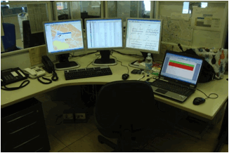
ATAF has a centralised control centre at the main depot. The Control Centre has a total of 4 active workstations, with a fifth available for development and training and system manager. Li-nea operates a separate control centre for its services.
A different set of ATAF routes are assigned to the various workstations.
Tasks and Priorities
The tasks of the Control Centre and the dispatchers are identified as:
- Supervise the operations of the public transport lines
- Adhere as much as possible to schedule and control the micro irregularity
- Ensure that driver handovers and meal breaks occur on time
- Manage incidents, accidents and emergencies
- Co-ordinate internal information, including information with drivers, street inspectors/mobile units (‘troubleshooters’)
Operations Procedures and Support Tools
The Dispatcher has a wide range of screen options available. These include:
- Detailed individual line view
- Route map
- Map showing multiple overlapping routes
- Tables of line condition and details
- Tables of vehicle and sensor condition and details
- Alarm and alert tables
- Timetable presentation
- Configuration options
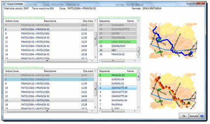
One of the primary screens for the Dispatcher is the individual line view:
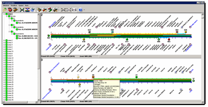
This can show one or more lines (i.e. routes), as requested by the Dispatcher.
- The route is shown in linear format, with all of the stops identified.
- The actual locations of the individual vehicles are shown
- The vehicle icons are colour coded to indicate their position relative to their schedule
- The outmost (upper and lower) lines are colour-coded to indicate the condition of the intervals between successive buses. This alerts the dispatcher to bunching and to excessive headways.
- The inner two lines are colour-coded to indicate the rolling average of the travel time on pre-defined route segments. This alerts the controller to sections where delays (relative to scheduled sectional running time) have been occurring.
- Passing the cursor over any vehicle brings up summary information, as shown above.
- Right-click of the cursor over any vehicle brings up more detailed information
A consist colour-coding is used across all screen views
- Cyan (blue) is used to indicate early running and bunching
- Green is used to indicate on-time running and within tolerance headways
- Orange is used to indicate moderate slippage
- Red is used to indicate late running or excessive headways
The Dispatcher can reduce the amount of information displayed on the screen. After several months of operation, the Dispatchers have become accustomed to it and can assimilate the information, and tend to opt for the full information set.
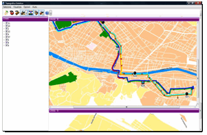
The Dispatcher can view the service in map form, either for an individual line or for multiple lines. The multiple line view (right) is particularly useful where there are overlapping lines. For example, if excessive headways occur on one route, the dispatcher can check whether a bus on another line with similar destination is filling the gap. Alternatively, if the Dispatcher would like to either turn a bus short or operate a bus out of service for part of the route, he can check whether that time period is adequately covered by another route.
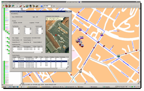
The Dispatcher can take a more detailed map view, to street and stop level, either in schematic or GoogleMap view. He can also view the specific location of one vehicle, or of all the vehicles assigned to a route. He can also use this view to see the assigned parking position of the vehicle in the depot.
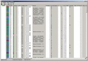
The dispatcher can opt for a tabular view (right), which lists all of the buses by route and duty, and provides a wide range of data on service, status, next trips, sensor conditions, etc. The Dispatcher can configure the view, and choose which columns to display. In practice, it has been found that the individual Dispatchers tend to set up the information differently.
Another set of utilities allows the Operations department to prepare planned diversions (“Macro-irregularities”). Normally this is done for roadworks, closures and other diversions approved and advised by the City. It can also be done as fallback scenarios for specific parts the lines.
The Operations department uses the mapping utility to identify the revised routing, to activate/deactivate stopping places, to adjust the running times, and to program in the applicable dates/time of the diversion. The system recalculates the schedule and reference data, which is then uploaded to the on-bus computers. This ensures that both the driver console and the visual/voice stop announcements are updated and correct.
Applications for which ITS is used at ATAF
ITS is used for the following applications at ATAF:
- Automatic Vehicle Location
- Operations Management, including Incident Management
- Real-time passenger information pre-trip, at stations and in vehicles
- Vehicle and driver scheduling
- Fare collection (for pre-paid tickets only, no on-bus ticket sales)
- Data generation for performance monitoring and contract reporting
ITS has been or is being implemented on a limited basis for the following applications, with the possibility to deploy on a wider scale:
- In-vehicle video-surveillance
- Traffic signal priority
- Automatic passenger counting
ITS supports and/or exchanges data with the following:
- Driver rostering
- Travel and traffic information
- Maintenance planning and management
Evolution of ITS at ATAF
ATAF was an early implementer of ITS. It introduced its first AVLC system in 1984, covering 100 vehicles in its fleet. The technology was based on intelligent in-vehicle units relaying position and status information to a central control centre, and also supporting voice communication.
A second generation of ITS was implemented in 1996, when ATAF participated in the JUPITER project of the THERMIE program of the former EU DG Energy . This extended the AVLC to the full fleet of 400 buses.
The overall system, based on platform technology was intelligent in-vehicle units using GPS for automatic vehicle location, and communication via private trunked mobile radio contracted to Italtel, a national communication company (which exited the market after 5 years). The AVLC control room software was subcontracted to Mizar, an Italian ITS systems supplier (currently part of SWARCO group.
Also in 1996-7, ATAF implemented ITS-assisted Demand Responsive Transport (DRT), within the framework of the SAMPO project of the EU’s 5th Framework Program. The PersonalBus system was supplied by Softeco, a Genoa-based firm. The PersonalBus system included:
- booking and reservation software
- route optimizing software
- dispatching software
- in-vehicle terminals for drivers, which included trip information, directions, passenger manifests, etc.
In 2003, GSM communication capability was added to in-vehicle radios to allow GSM for voice communication, thus relieving problems of insufficient voice channel capacity on the private radio (see section below on Communications).
In 2006, a new generation of ITS was procured based on GPRS/UMTS communication network, with complete replacement of all the existing AVLC-related systems (in-vehicle, control centre and back-office hardware and software), and the provision of new RTPI and other sub-systems.
Following a public procurement process, the supply contract was awarded in 2009 to Elsag Datamat, a subsidiary of Finmeccanica. In contrast to the previous generations of ITS, there is now a single supplier for all aspects of the AVLC system. (ATAF notes that it has been a trend among the European ITS suppliers of both in-vehicle and control centre ITS to expand their offer to the full system, either by in-house development or acquisition).
The functional and technical requirements of this procurement reflected the operational and reporting requirements under the Service Contract with Province of Florence, and also the operational, administrative and shared responsibility aspects of the S.C.a.R.L.
A single procurement was conducted (from end-2006 to end-2008) for the systems to be used at both ATAF and Li-nea, although each company would sign an individual contract with the supplier for the equipment they receive.
The procurement, from the technology point of view, covered the following:
- Control centre system including software and 7 workstations (ATAF and Li-nea)
- A Front End Processor based on GPRS/GSM network for interfacing the dialogue among the buses and the control centre
- In-vehicle AVLC and related equipment for 443 buses plus 20 support vehicles at ATAF
- In-vehicle AVLC and related equipment for 93 buses plus 5 support vehicles at Li-nea
- Depot equipment, including WiFi communication to vehicles for data transfer (4 at ATAF, 2 at Li-nea)
- In-vehicle video-surveillance for 20 vehicles
- 30 free-standing bus-stop panels for RTPI
- 50 in-shelter display panels for RTPI
- Web portal and SMS applications for RTPI and other travel information
This is illustrated in the System Architecture diagram below.
The system is currently being deployed in a step-wise manner, beginning with the AVLC Control Centre followed by the in-vehicle AVLC equipment, with the other in-vehicle and at-stop devices to follow.
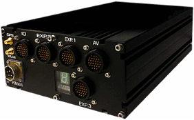
ITS Equipment and Devices
In-vehicle ITS-related equipment consists of:
- On-board computer
- GPS
- GPRS/GSM (voice, data) card and antenna
- WiFi (wireless LAN) for in-depot data transfer
- Driver’s console
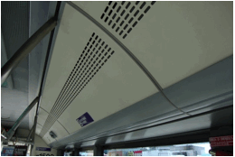
- Display screens for RTPI
- Voice announcer (interior)
- External destination board
- Forward-facing camera for photographing vehicles violating bus lanes
- CCTV (currently only on about 20 vehicles)
- Automatic Passenger counters (currently only on about 20 vehicles)
The configuration of the on-board ITS is shown in the figure below.
Station/stop equipment ITS-related equipment consists of:
- Displays for RTPI
- Self-service ticket vending machines
- Depot ITS-related equipment consists of:
- WiFi (wireless LAN) for data exchange with vehicles
AVL and Operations Management
The ITS for AVL consists of four main elements:
- On-board integrated computer
- Driver console
- Control centre workstations
- Control centre software
On-board integrated computer
The on-board integrated computer is the core of the in-vehicle ITS systems. The key functions are:
- hosts all the reference data required by in-vehicle systems and peripherals
- stores the transaction data and logs for transfer to the depot
- manages the in-vehicle network
- hosts the GPS card and odometer input
- hosts the GSM/GPRS and WiFi communication cards
- hosts the VISOR video-surveillance processor card, and the soft/hard memory for video-surveillance images
The on-board computer has an Intel processor, 32Mb microprocessor, 128 Mb RAM and a further 256Mb flash memory. It has 13 serial ports.
The on-board computer is housed discretely behind a panel in the bus, with secure locking but easily accessible.
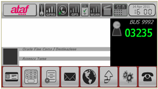
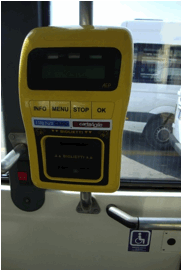
Driver’s Console
The driver’s console is consists of a high-definition, multi-function, touch-screen display. The console is a display unit, providing a user interface to the on-board applications, all processing and data storage functionality is in the on-board computer.
The console has multiple screen views, including:
- Initial sign-on
- Options Menu
- Normal driving mode
- Message menu to send information to the Dispatcher
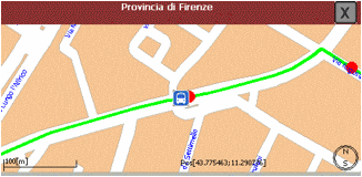
- Map and direction finder
- Designated parking location in the depot
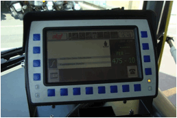
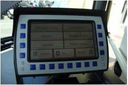
The schematic of the function screen is shown below:
The map and direction finder view is shown below. This can be set at different zoom levels:
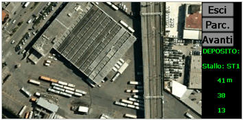
One of the more innovative screen views displays the assigned position in the depot where the driver should park the vehicle:
Communication
Mobile communications for AVLC has represented a challenge for ATAF throughout the history of their ITS deployment, primarily because of the constraints caused by the limited number of radio channels.
The core mode is private trunked mobile analog radio. There have just three channels available for both voice and data communication. As in many other European countries, in the late-80’s/early-90’s when the national authorities needed to restructure spectrum allocation to enable new services, ATAF were allocated different frequencies with narrower bandwidth.
When ATAF commenced AVLC operations in 1984 it was with 100 buses. When they extended the system to the full fleet of 400 buses in 1996, they began to experience constraints even after adopting a trunked mobile radio approach.
In 2003 they were facing serious problems with communications based on three radio channels. They transferred 100 vehicles to GSM for voice communication, with all data communication staying on the private radio channels. GSM cards were inserted in the existing radios. The switch between trunked mobile radio and GSM is done automatically, and is invisible to the Dispatchers and to the driver.
Commissioning of the new communication system started in 2009). It is based on the GPRS/GSM network. This brings benefits to the public transport operators (no infrastructure investment and maintenance costs, high level of service, rapid-response time for fault repairs, interventions, etc.). However, it also has some known drawbacks (points of low/no coverage, possibility to lose communication when cell is overloaded, difficult communication in emergency situations, etc.)
Separately, close range communication is performed by WiFi (wireless LAN), which is integrated into the on-bus computer. WiFi coverage is available throughout the depots, so vehicles can exchange data wherever they are (e.g. parked, at maintenance, at washing/fuelling).
Data transfer includes:
- Upload of reference data (routes, stops, schedule, …)
- Download of transaction data, statistics, logs, etc.
Real-time Passenger Information
Passenger information at ATAF consists of multiple strands:
- How to use the transport system
- Journey planners
- Real-time passenger information
- Incident information and alerts
Real-time passenger information is based on the AVL system. RTPI is provided through four main channels:
- Internet channels
- Mobile personal devices, with a combination of ‘push’ and ‘pull’ services
- At-stop displays
- In-vehicle displays
At stop information consist of two types of device:
- Free standing pole-mounted panel
- In-shelter panel
The roll-out is currently in delay, as not all of the buses are equipped with the new ITS system, and hence some cannot support the RTPI function.
RTPI in the vehicles is provided using scrolling-text single-line displays. The normal mode is to display the name of the next stop. They can also be used to display prerecorded messages or advisories from the Dispatcher.
All vehicles are equipped with voice announcers that can be used for stored information (normally announcement of the next stop), for driver messages, or for messages from the Dispatcher.
A range of SMS, WAP-enabled, and internet-based traveller information and RTPI services has been made available for use in personal devices (PCs, mobile phones, PDAs) by a dedicated real time web Portal.
Traffic Signal Priority
Currently there is not priority at traffic signals. As part of the new ITS system, 10 junctions will be equipped as an initial batch, with the intention that it will then be deployed on a wider scale.
The planned mode of operation is based on the vehicle making a direct request to the Urban Traffic Control (UTC) system for priority. It will work as follows:
The UTC system provides reference data to the AVLC system about all relevant traffic signals
The AVLC system includes this data in the reference information that is downloaded to all vehicles. In this way, the on-bus computer knows for each line where the signals are, whether give priority, and any relevant rules
As the vehicle progresses along the route, it knows when it will approach a traffic signal where priority is possible, it can forecast when it would arrive at that junction, and it knows whether it should request priority
When/if the vehicle should request priority, the vehicle automatically initiates a request for priority
This request is sent outside the normal polling cycle, and is sent directly to the UTC without being processed, checked or approved by the AVLC system.
It is not yet finalized whether the request would be routed directly to the UTC system, or channeled via the AVLC system, but in either case it is effectively a direct dialogue between the vehicle and the UTC system
The UTC considers the request and applies the applicable rules, both for the vehicle in relation to general traffic, and between public transport vehicles if more than one request is received
It is up to the UTC system whether to grant priority, and if so, in what manner
There are two technical aspects to be considered, and will only become clear when the demonstration junctions have been implemented:
The length of the transaction time from the moment the on-board computer initiates a request for priority, and the time the UTC actions its decision (which may or may not be to grant priority). This includes communication and processing time. The system supplier is satisfied that the total time will be very short, but it remains to be demonstrated.
The volume of additional messages, if extended to the full fleet across all traffic signals in Florence. Currently, vehicles are polled for AVL purposes at 30-second intervals. Initial estimates by the supplier indicate that the volume of the communications for Traffic Signal Priority requests could be in the same order of magnitude as for the normal AVL polling. If this should be the case, it would be a substantial communication burden.
Video-surveillance
Video-surveillance facilities are installed in 20 buses as part of the current ITS implementation.
The standard installation consists of 3 CCTV cameras linked to a VISOR card that has been added to the on-board computer.
The normal mode is for the images to be stored in erasable memory, and then overwritten. If the driver presses the alarm button, the images are recorded in hard memory and are retained until such time as they are recovered or manually erased.
Images that have been recorded to hard memory are recovered manually, even though they could be transferred over the WiFi link. The reason for this is to preserve the ‘continuity of evidence’ in case the images ever need to be used in court or for other formal purposes (i.e. by the time the images are presented in Court, there is a certifiable chain back to initial generation of the images where each person in the chain can attest how the images were transferred to him/her and that they were stored and/or transferred in a manner whereby they could not have been altered or otherwise interfered with).
It is possible to view images from vehicles in real-time, although this facility would only be used in exceptionally cases. The bandwidth required for image transfer is high, and it would have to be done over the GSM facility, which is not suitable for such transfers. To make it practicable, it would be sent as a sequence of still-shots, sufficient for the Dispatcher or other authorized person to be able to discern what is happening on the vehicle.
Other Imaging Technologies
Vehicles are equipped with forward facing cameras so they can capture images (including licence plates) of vehicles obstructing bus lanes and other public transport facilities.
Automatic Passenger Counters
About 20 buses have been fitted with Automatic Passenger Counters. These are used as ‘laboratory buses’ and are rotated across the fleet to periodically survey all routes.
ATAF have not been sufficiently confident in APC technology to install it as standard across the full fleet.
Scheduling
ATAF uses Microbus as their scheduling package.
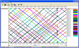
The AVLC system can generate graphics of the timetable, and the actual performance in service. They can track the deviations and consider what adjustment, if any, need to be made to the total or sectional running times. They can also replay the operation of an individual bus or a whole route for a period of time, to try to understand the dynamics of the service and see whether it can be improved through the schedule.
Fare Collection
There is no fare collection or tickets sold on-board ATAF services, and hence there are no ticket issuing machines on the vehicles. All tickets must be pre-purchased.
Each vehicle is equipped with smart card readers, provided by AEP, an Italian ticketing validator supplier These are linked to the on-bus computer, which receives the transaction data, stores it, and then transfer it in the WiFi download at the depot. The standard configuration is two smart card readers, located within the vehicle. The readers are supplied by a different firm to the main AVLC supplier.
System Integration
All applications are fully linked and integrated. The on-bus computer provides full integration and data consistency of all in-vehicle devices.
The system architecture has been developed by the supplier, albeit reflecting ATAF’s specifications, and integration is achieved by the supplier.
The architecture and interfaces reflect European project concepts and CEN TC278 standards, although the actual implementation is the supplier’s proprietary approach. The supplier uses its own data model.
Management and Oversight of the ITS Systems
The ITS system is implemented, managed and overseen by ATAF.
ATAF has developed an in-house team of 5 persons supported by an external technical advisor MemEx (an independent engineering company). This team has built up considerable ITS experience.
The supplier is responsible for system supply, maintenance, technical support and developmental support. The maintenance and technical support are provided by the supplier and have not been outsourced.
Service Level standards for the ITS applications
Technical service level standards have been specified in the ITS system supply contract.
This information has not been made available.
Implementation and Operational Experience
System commissioning commenced in 2009. The new ITS system is being deployed on a phased basis. The AVLC Control Centre has been implemented, the AVLC and communications are in roll-out phase, and the in-vehicle peripheral devices, RTPI and Traffic Signal Priority will follow.
This leads to a transition period in terms of systems, vehicles equipped, operational methods and training/capacity. ATAF consider that these are transition issues that are being, and will be overcome.
At present, there is a mix of new and old in-vehicle ITS equipment. The old ITS equipment cannot support some of the functions, and does not provide some of the information needed by the AVLC Control Centre system. This requires the Dispatchers to be aware of these limitations, and to try to manage the mix of vehicles assigned to the routes. The AVLC displays indicate which vehicles have the new and old systems. One particular issue is that the new system cannot make voice calls to the old system, requiring the Dispatchers to use a special phone.
A further issue is the impact on the RTPI rollout. When some vehicles are not able to support the RTPI function, then it diminishes the quality and value of the forecast arrival times as some buses are missing from it.
Installation is taking a considerable time. As almost all of the buses require new wiring for the ITS, and there are many peripheral devices to be provided for, it takes approximately a full day per bus. It has only been possible to release two buses per day for installation without compromising the service offer, thus limiting the pace of installation. At time of writing (May 2011), about 40% of the fleet has the new ITS fully installed. The approach has been to make the conversion by bus model type.
ATAF notes (from observation of the offers in the recent procurement) that suppliers tend to significantly underestimate the time and cost of installation of the ITS systems, and fail to adequately budget for it. They recommend that care is taken on this item, as either the supplier will lose on this aspect or it may become a source of tension between the Client and the Supplier.
The Dispatchers have had to become familiar with the new Control Centre software, which has major conceptual, visual and functional change compared to the previous system. They have received training and a supplier’s representative was required to be available at the Control Centre. This transition is ongoing.
Three features of the new AVLC Control Centre are novel (not only to ATAF), and will require some experience to gain their full value:
Dynamic rescheduling, which allows the Dispatcher to add or remove a vehicle for a specified period (trip, duty, time period) or to implement exception management (turn a trip short, run out of service). The AVLC system recalculates the route and schedule. In addition to providing the Dispatcher with a dynamic operational tool, it also records the event for the Service Contract reporting.
Computer-assisted regulation strategies. The AVLC can identify problems and can suggest strategies/actions to the Dispatcher. It remains the Dispatcher’s judgement call whether to implement the suggestions.
Dispatcher action profile analysis. The AVLC can generate a profile of the performance of the services managed by an individual Dispatcher and the regulation actions implemented. This can be compared to a baseline or to the profile of other Dispatchers on the same or different routes. The profile comparison can be used to see whether some workstations are overloaded and to try reassigning some routes. It can also be used to see whether the services are not performing as well under an individual Dispatcher, or whether there is excessive regulation. This could be used as the basis for review and retraining.
Capital Costs of the ITS
This data has not been made available.
Operating Costs of the ITS
This data has not been made available.
Revenue Generated by or through the ITS systems
No revenue is currently generated through the ITS systems.
There is potential to exploit the RTPI channels to generate revenue from advertising, but this is not currently under consideration.
Benefits arising from the ITS systems at PRTC
There has not been a comprehensive CBA or other appraisal of the benefits of the ITS system.
Nonetheless, ATAF considers that it has received considerable benefits from the ITS implementation, especially the AVLC system. They consider that this has greatly improved both their operational management capacity and the information for performance analysis and service planning.
ATAF also notes the reporting requirements in relation to the Service Contract with Province of Florence, and that it would be extremely difficult or impossible to achieve these properly with the AVLC.
Images
Screen-shot and schematic images courtesy of Elsag Datamat.